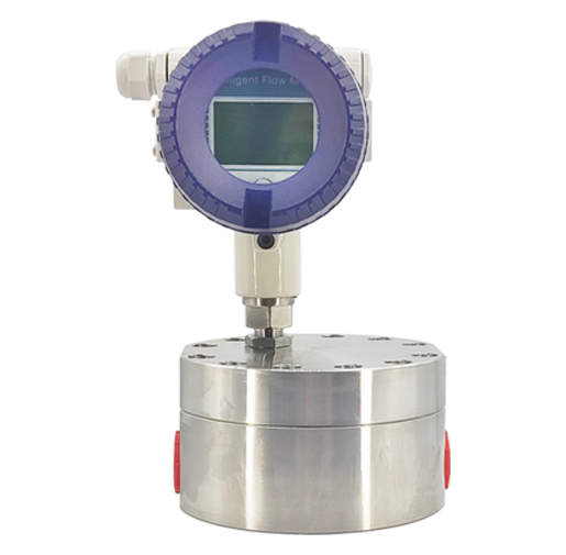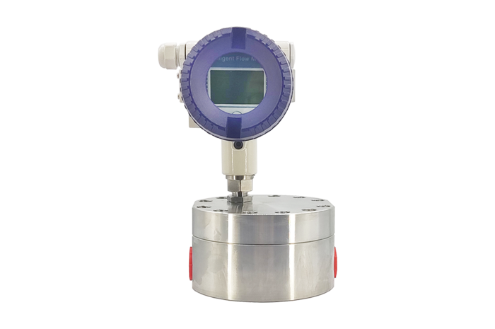
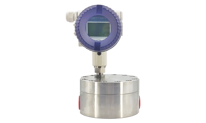
ATGF Gear Flow Meter
Measuring Medium:
oil, brake fluid, special hydraulic working oil, diesel oil ,lubrication
Viscosity Range:
1~100000cSt
Temperature:
-60℃~+150℃
Working Pressure:
40MPa
A new volumetric flowmeter developed under the principle of gear motor, used for precise continuous or intermittent measurement of the flow of liquid in the pipeline or Instant flow rate, suitable for heavy oil, polyvinyl alcohol, resin and other high viscosity medium flow rate measurement, small flow rate can be accurately measured.
.png)