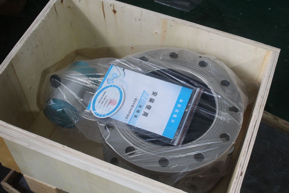
Vortex flow meter installation and use instructions
2024-11-05
Vortex flow meter installation environment requirements:
1. Avoid high-voltage equipment, high-frequency equipment, and strong switching power supply equipment as much as possible. The power supply for the meter is as separate as possible from these devices.
2. Avoid the direct influence of high temperature heat sources and radiation sources. If it must be installed, it must be insulated and ventilated.
3. Avoid high humidity environment and strong corrosive gas environment. Ventilation measures should be provided if installation is necessary.
4. Vortex flowmeters should be avoided as far as possible installed on pipelines with strong vibration. If it must be installed, pipe fastening devices must be installed in upstream and downstream 2D, and anti-vibration pads should be added to strengthen the anti-vibration effect.
5. The instrument is installed indoors, and should be waterproof when installed outdoors. Special attention should be paid to bending the cable into a U-shape at the electrical interface to avoid water entering the amplifier housing along the cable line.
6. Adequate space should be left around the instrument installation point for installation wiring and regular maintenance.
Vortex flow meter pipe installation requirements:
1. Vortex flow meter has certain requirements for the upstream and downstream straight pipe section of the installation point, otherwise it will affect the flow field of the medium in the pipeline and affect the measurement accuracy of the instrument.
Note: The regulating valve should not be installed at the upstream of the vortex flow meter as far as possible, but should be installed at the downstream 10D of the vortex flow meter.
2. The upper and lower pipe inner diameters should be the same. If there is any difference, then the inner diameter Dp of the piping and the inner diameter Db of the vortex meter should meet the following relation 0.98Db≤Dp≤1.05Db The upper and downstream piping should be concentric with the inner diameter of the flow meter, and the difference between them should be less than 0.05Db.
3. The gasket between the instrument and the flange shall not be convex into the tube during installation, and its inner diameter shall be 1-2mm larger than the inner diameter of the meter.
Installation steps of vortex flowmeter
1. The opening is made on the pipe according to the requirement of the opening length, so that the position of the opening meets the requirement of the straight pipe section.
2. Place the complete flow meter with the upper flange into the open pipe.
3. Spot welding is performed on both sides of the two flanges. Remove flowmeter, weld flange as required, and clean all protrusions in pipe.
4. Install a sealing gasket with the same diameter as the pipe in the inner groove of the flange, load the flowmeter into the middle of the flange, and make the flow direction of the flowmeter mark the same as the fluid direction, and then connect it with bolts.
Installation of vortex flowmeter on horizontal pipeline: When measuring gas flow, if the measured gas contains a small amount of liquid, the flowmeter should be installed at a higher point in the pipeline.
When measuring liquids, if the measured liquid contains a small amount of gas, the flow meter should be installed in the lower part of the pipeline.
Installation of vortex flowmeter in vertical pipe: When measuring gas, the flowmeter can be installed on the vertical pipe, and the flow direction is unlimited. If the measured gas contains a small amount of liquid, the gas flow should be from the bottom up. When measuring the liquid flow direction, the liquid flow direction should be from the bottom up.
Vortex flowmeter installation should pay attention to matters
1. The installation of the flow meter must be carried out as required to avoid damage to the instrument due to improper installation and affect the measurement accuracy.
2. The flow meter should be avoided as far as possible to install on the overhead long pipeline, because the sag of the pipeline is easy to cause the sealing leak between the flow meter and the flange. If it is necessary to install, pipe support points must be set in the upstream and downstream 2D of the flow meter. If the measured medium needs to be compensated for temperature and pressure (such as steam and compressed air), the pressure measurement point should be confined to the downstream of the flow meter at ~5D, and the temperature measurement point should be in the downstream of the flow meter at 4-8D
3. In the pipeline for measuring steam, in order to prevent the temperature of the converter from being too high, at least half of the instrument connection rod should not be insulated. In order to facilitate observation and wiring, the meter head can be rotated 360 degrees on the original position, and the lock nut can be tightened after adjusting the position. If the meter head is installed in a downward direction, wrap the locking nut with waterproof tape to seal it. If you want to know more about the flow meter or flow meter selection, please consult the Aister flow meter manufacturer email: sales@aistermeter.com for help.
Share To:
News
- Why is the thermal gas mass flowmeter not affected by pressure strength and temperature?
- What to do when a thermal gas mass flow meter fails?
- How are thermal gas mass flow meters used? What are the applications?
- Under what circumstances is the gas measurement need to be regulated compensated vortex flowmeter
- Why Is The Aister Thermal Gas Mass Flowmeter So Popular ?
- Gas turbine flowmeter manufacturers explain their main advantages in measurement
- Gas turbine flowmeter manufacturer Aister instrument field experience summary
- Aister Instrument Empowerment Conference


