What failures occur during installation and commissioning of electromagnetic flow meter?
In the electromagnetic flowmeter installation and debugging stage there will be some failures, below, we will understand the specific causes of the failure at this stage and their elimination methods.
Failure caused by incorrect installation
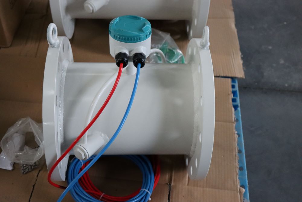
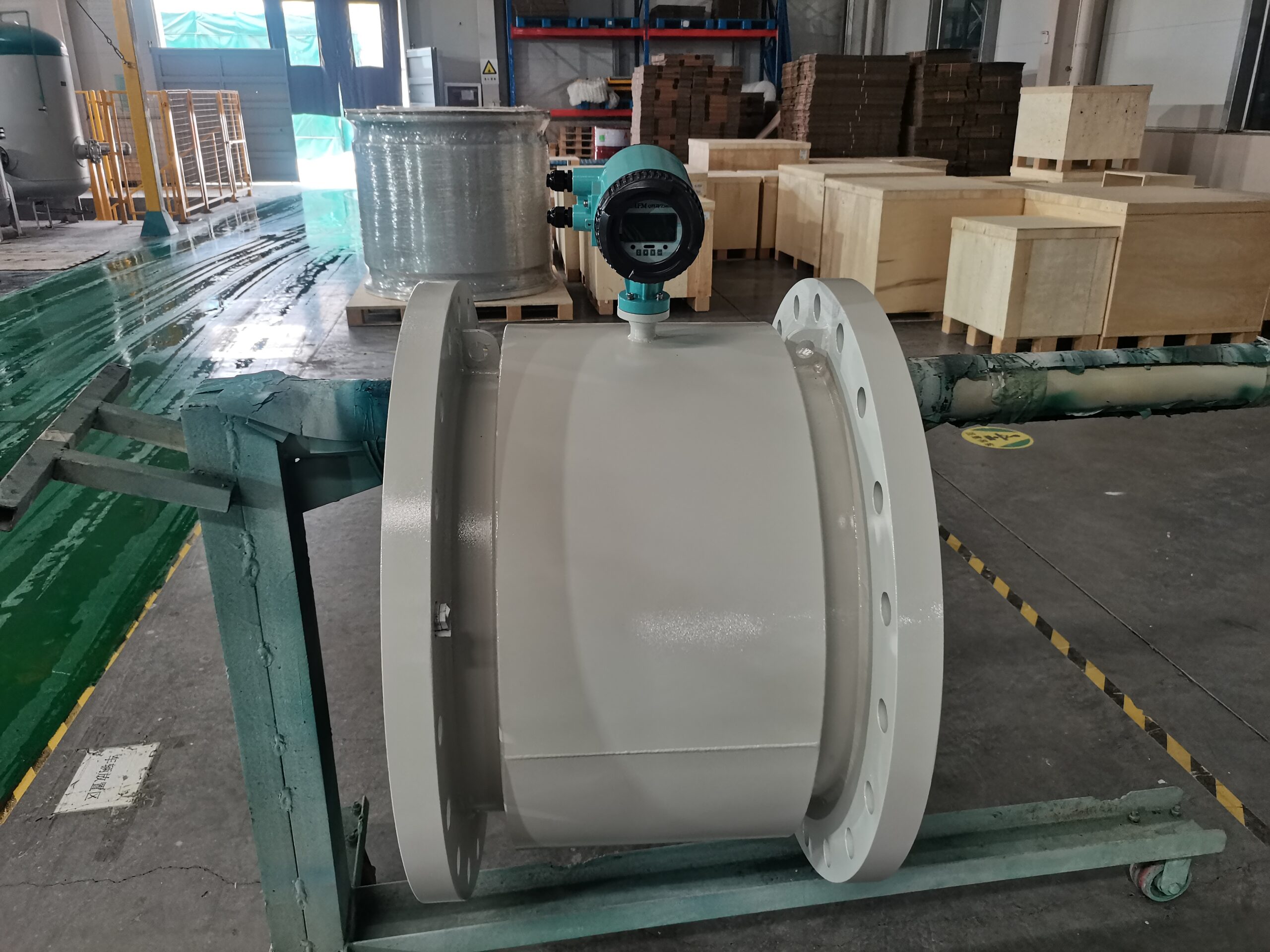
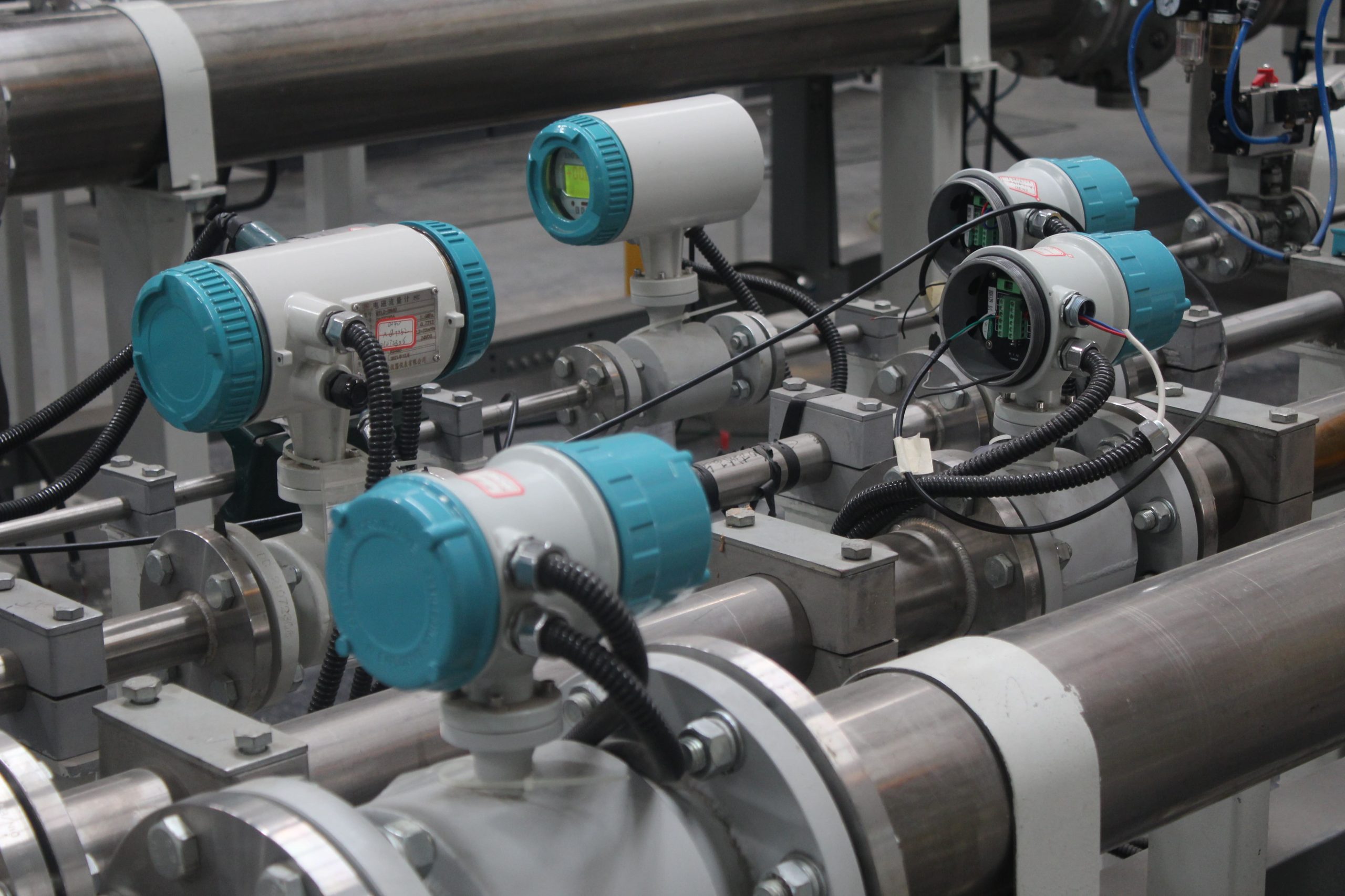
The incorrect installation position of the electromagnetic flowmeter may cause the fluid to enter the atmosphere and cause the measuring tube to be not full, so the sensor is installed vertically as far as possible during the installation, so that the measured medium flows through the flowmeter from below to above, such as the flowmeter must be installed horizontally, it should be ensured that the axis of the electrode and the ground are parallel. Whether horizontal or vertical installation is used, bypasses and valves should be provided at both ends of the sensor to facilitate the maintenance of the electromagnetic flowmeter. It is necessary to install the regulating valve to the downstream of the flow meter and the pump source to the upstream of the flow meter to ensure the measurement accuracy of the flow meter.
Fault caused by environmental factors
When there is large motor magnetic field interference, space strong electromagnetic wave interference and pipeline stray current interference in the environment, it will cause the failure of the electromagnetic flowmeter, so the existence of these interfering factors should be avoided in the installation site. Space electromagnetic wave interference is generally introduced by the signal cable, so it is necessary to use single or multi-layer shielding to avoid the introduction of the interference signal. In order to avoid interference caused by stray current, it is necessary to carry out good grounding protection, and insulate it from the flow sensor and pipe. At the same time, attention should be paid to avoid violent vibration and the existence of strong AC and DC magnetic fields in the installation site.
Measuring faults caused by the medium
If there is a uniform distribution of tiny bubbles in the liquid to be measured, the normal operation of the electromagnetic flowmeter usually does not affect, but when the bubble increases to a certain extent, it will cause fluctuations in the output of the flowmeter, if the bubble increases enough to cover the entire electrode surface, the bubble flow through the electrode loop will produce an instant short circuit, resulting in greater signal fluctuations. When measuring mixed media, if the measurement is not fully mixed and uniform, it will cause fluctuations in the output signal, so pay attention to the mixing situation when measuring the mixed media.

-.jpg)
-.jpg)


