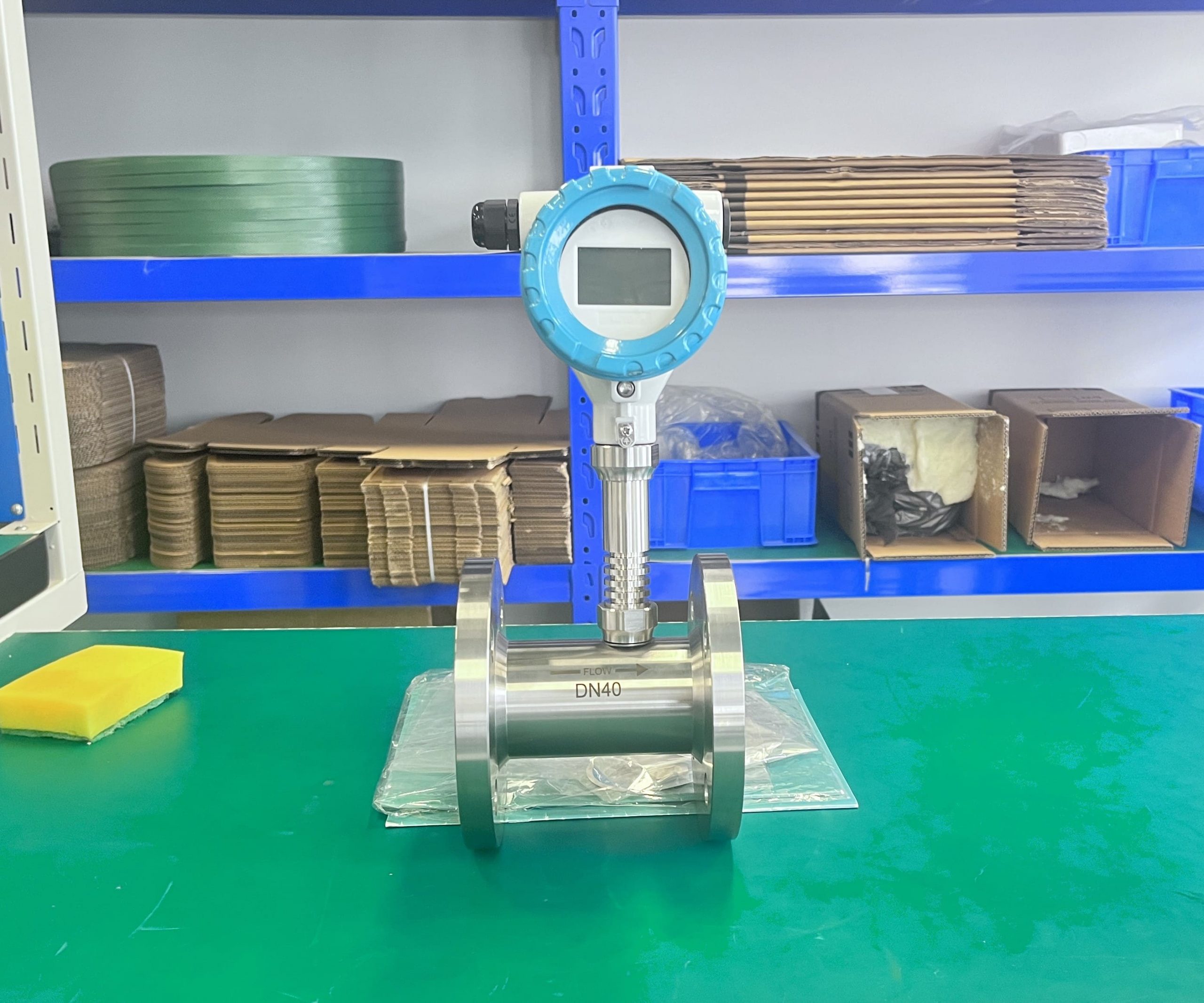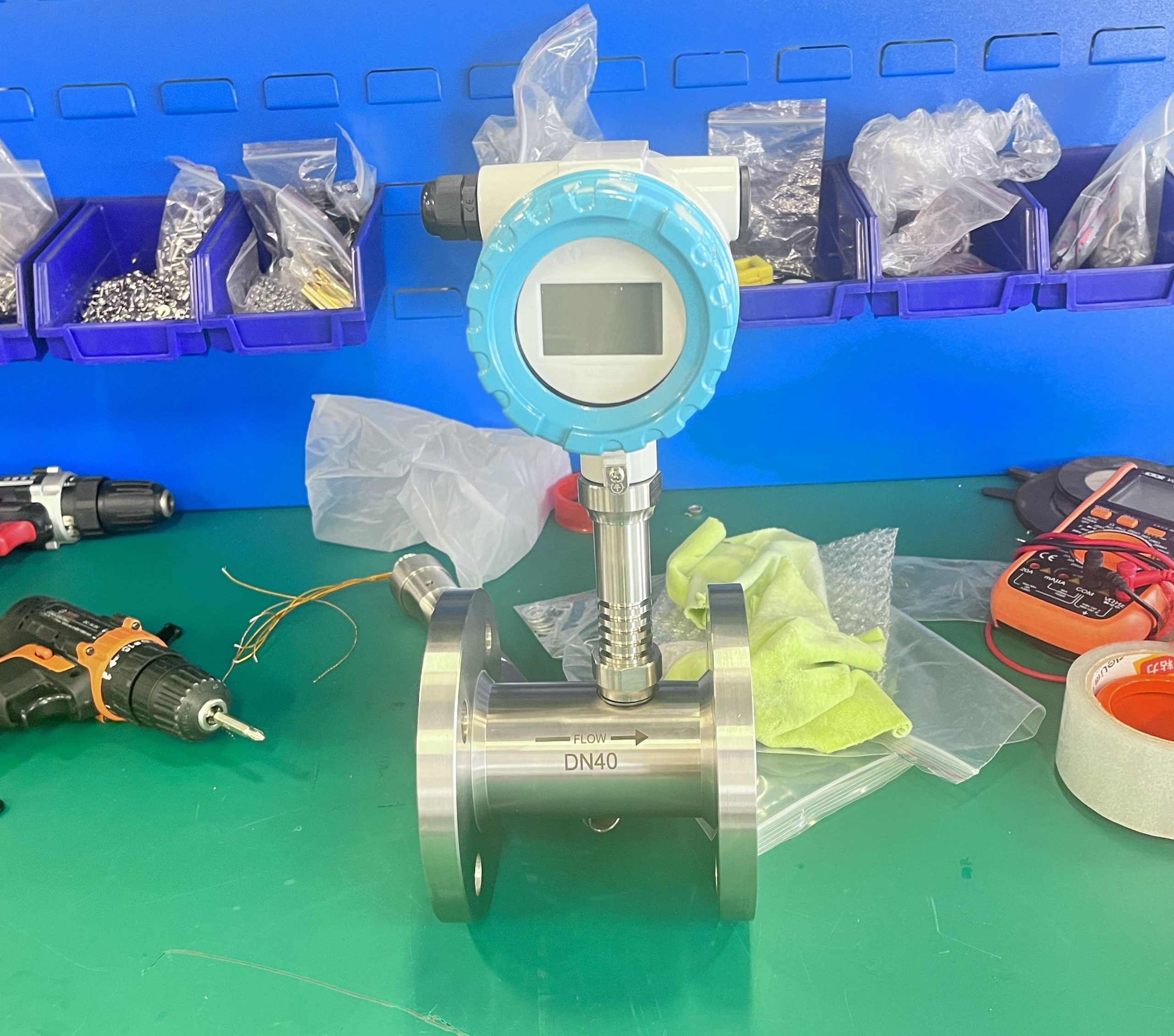
Turbine flow meter installation precautions
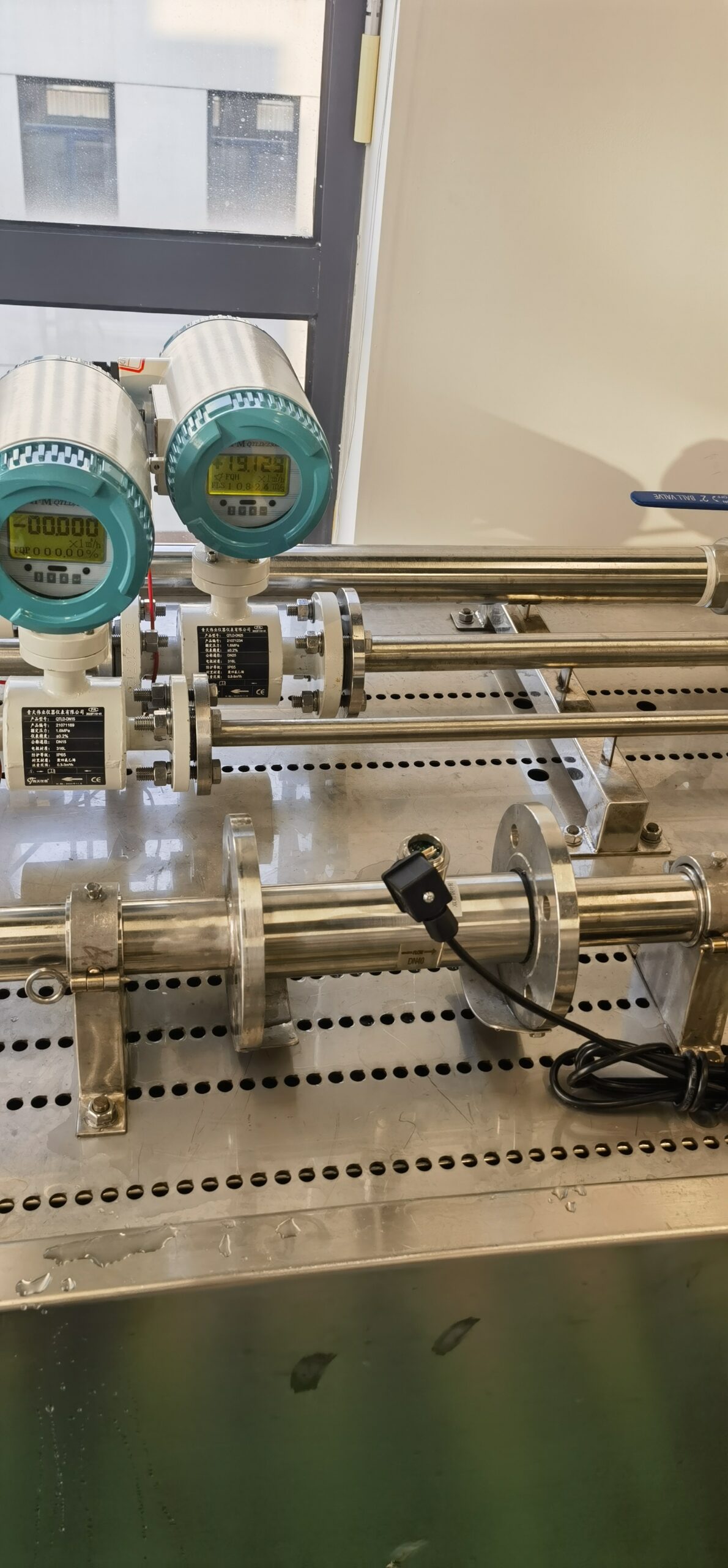
(1) The horizontally installed sensor of the turbine flowmeter requires that the pipe should not have a visually perceptible tilt (within 5°). The vertical deviation of the vertically installed sensor pipe should be less than 5°, and the fluid direction should be down and up.
(1) The horizontally installed sensor of the turbine flowmeter requires that the pipe should not have a visually perceptible tilt (within 5°). The vertical deviation of the vertically installed sensor pipe should be less than 5°, and the fluid direction should be down and up.
(2) Where the flow cannot be stopped, bypass and stop valves should be installed. If the fluid contains impurities, the filter should be installed on the upstream side; If it contains gas, an air eliminator should be installed on the upstream side. Filter and degasser outlet and degasser outlet should lead to a safe place.
(3) The flow control valve of the turbine flowmeter should be installed in the downstream of the sensor, and the upstream stop valve should be fully opened when measuring, and should not produce vibration and leakage. A check valve should be added to prevent reverse flow of fluid for processes that may produce reverse flow.
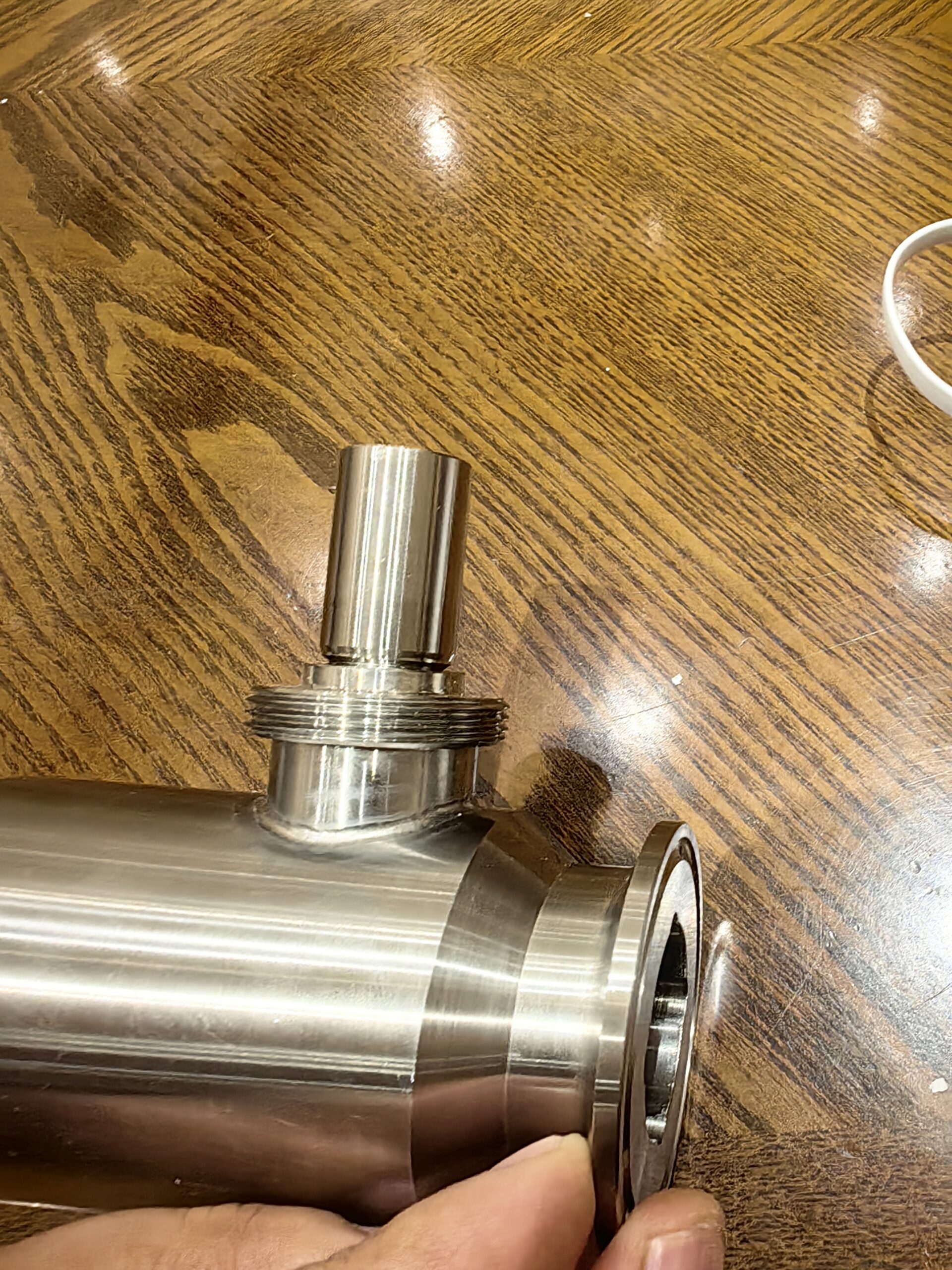
(4) The sensor should be concentric with the pipeline, and the sealing washer should not be protruded into the pipeline. The sensor should not be higher than the level of the pipeline, so that the gas gathered in the pipeline (such as mixed air when the flow is stopped) stays at the sensor, which is not easy to discharge and affect the measurement.
(5) The pipes before and after the turbine flowmeter sensor should be supported firmly and do not produce vibration. Heat preservation measures should be taken for the sensor and its front and rear pipes for the easily condensable fluid.