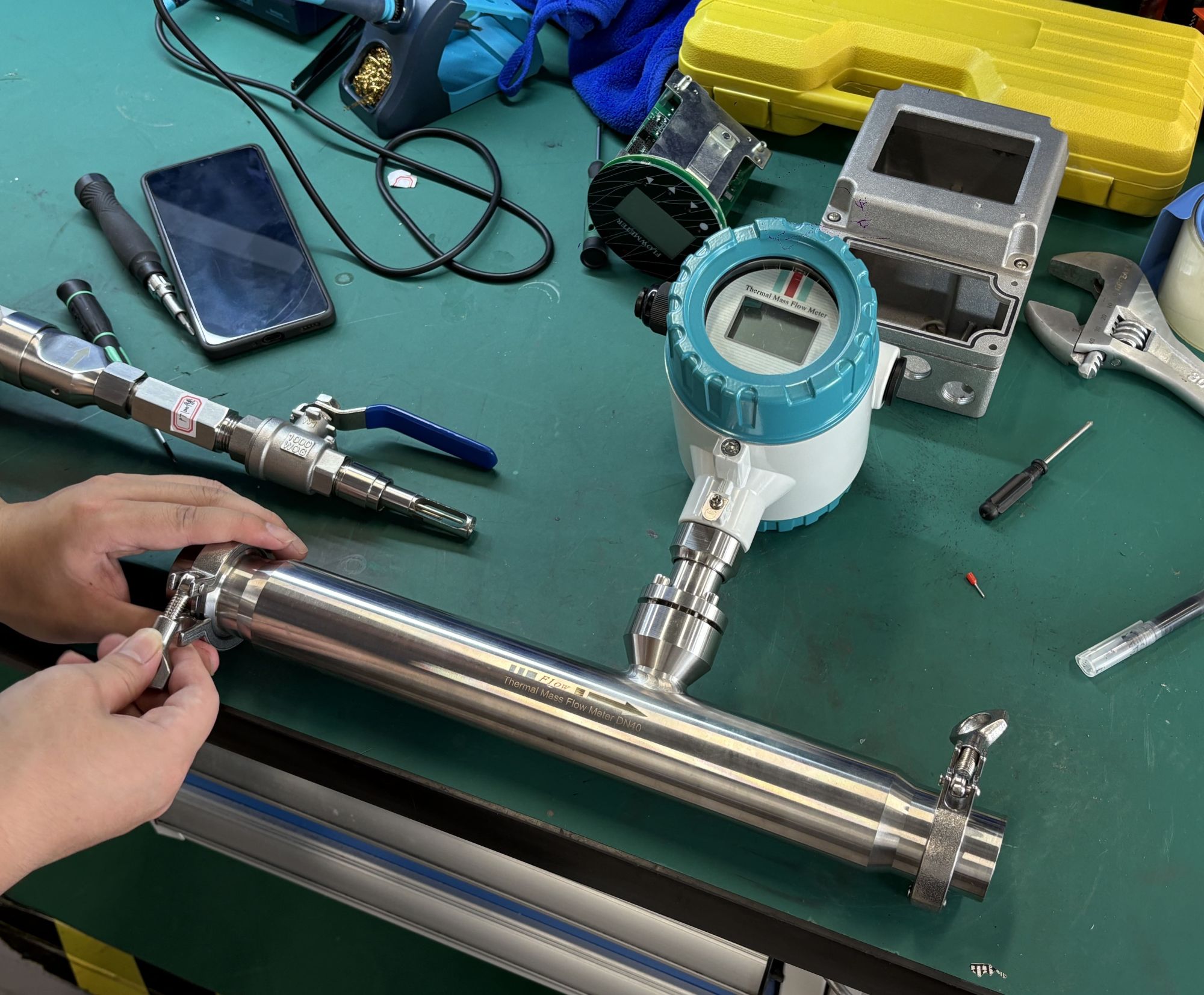
How to install a thermal gas mass flow meter?
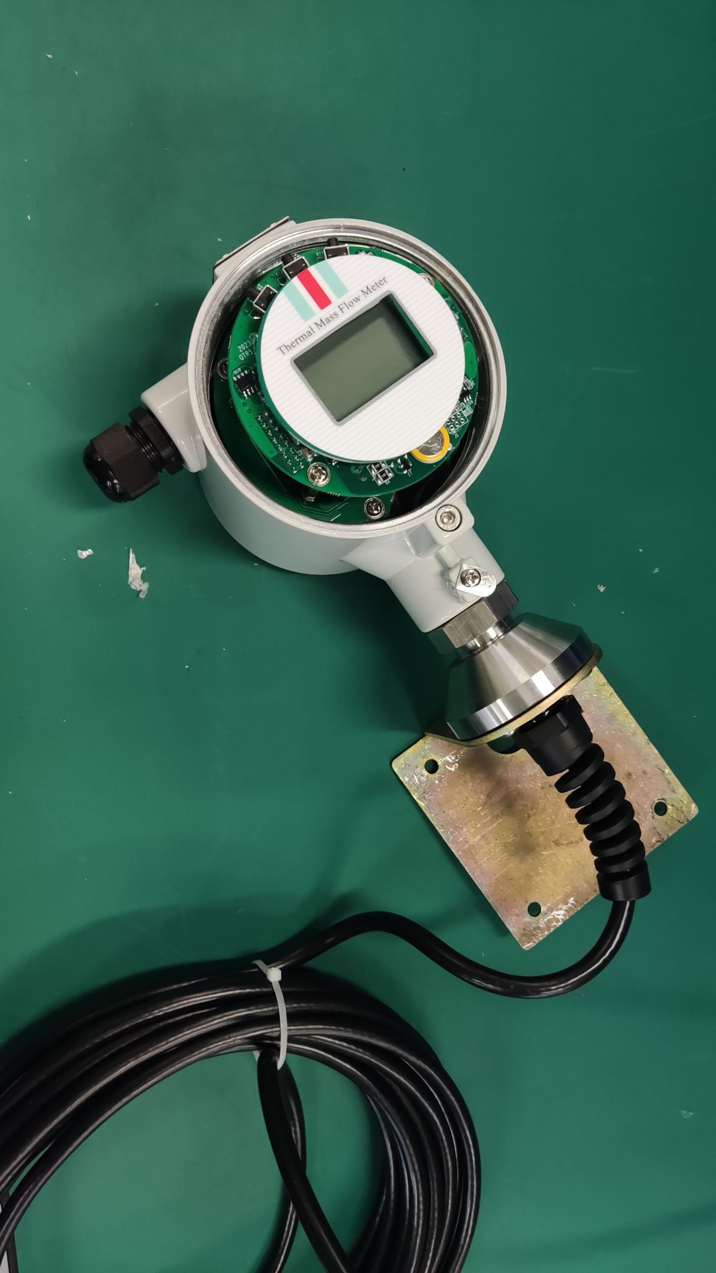
Thermal gas mass flowmeter adopts the principle of thermal diffusion, and thermal diffusion technology is a technology with excellent performance and high reliability under harsh conditions.
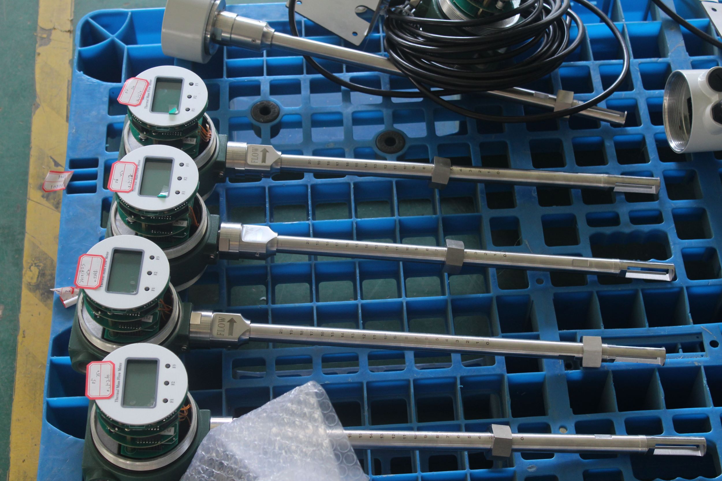
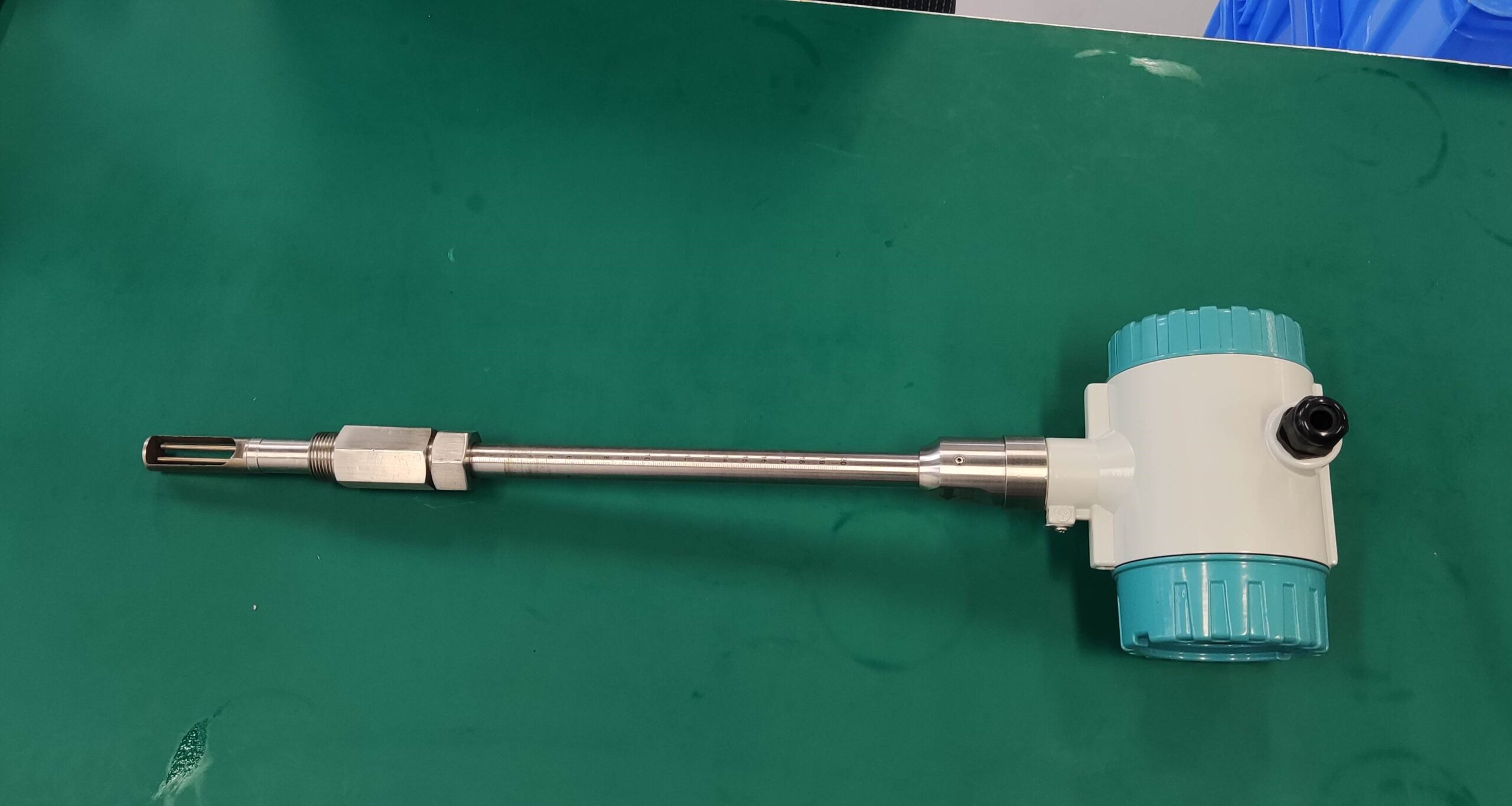
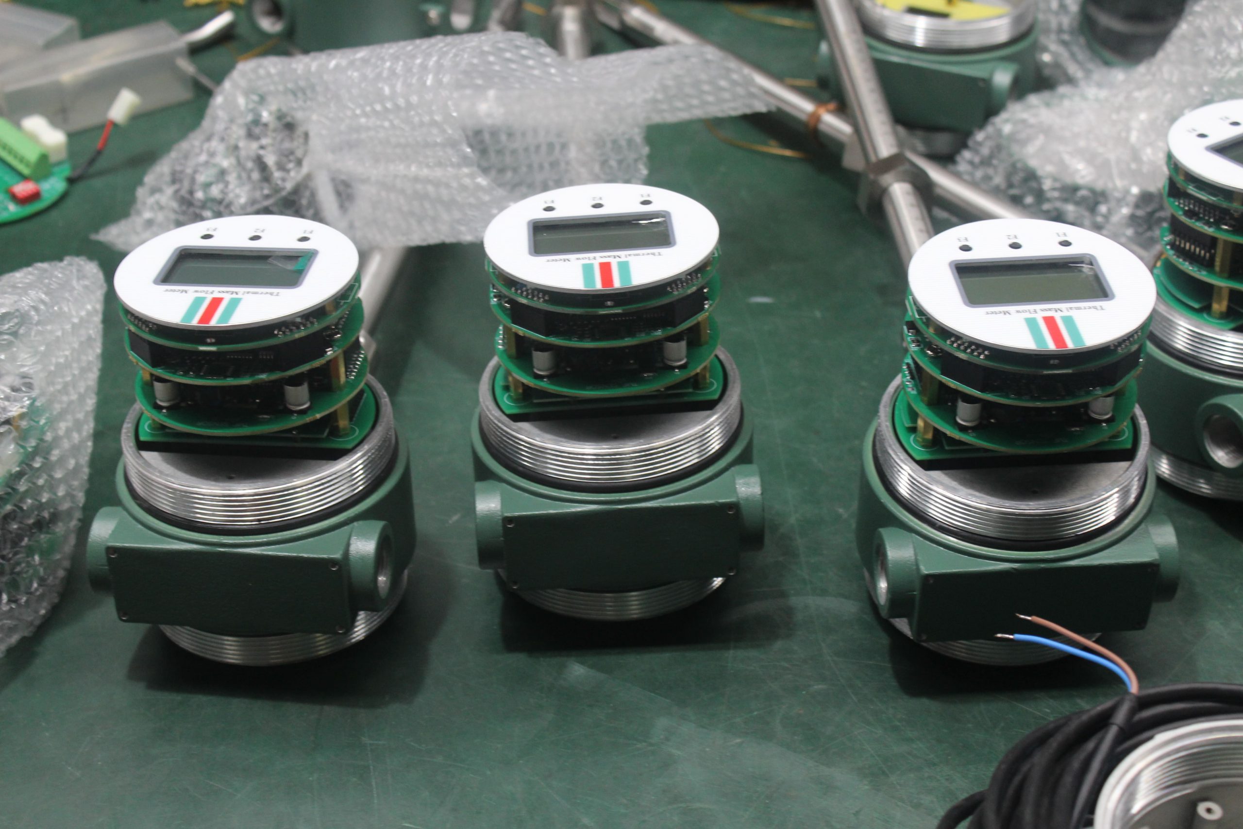
Thermal gas mass flowmeter adopts the principle of thermal diffusion, and thermal diffusion technology is a technology with excellent performance and high reliability under harsh conditions. Typical sensing elements include two thermal resistors (platinum RTDS), a speed sensor and a temperature sensor that automatically compensates for changes in gas temperature. When two RTDS are placed in a medium, where the velocity sensor is heated to a constant temperature above the ambient temperature, the other temperature sensor is used to sense the medium temperature. The mass flow of gas through the velocity sensor is calculated by the heat transfer of the sensing element. As the gas flow rate increases, the heat carried away by the medium increases. The temperature of the sensor decreases accordingly. In order to maintain a constant temperature, the working current through the sensor must be increased, and the increased part of the current is proportional to the flow rate of the medium.
On-line installation of hot gas mass flowmeter:
1. For installation details and layout, use rs485 output.
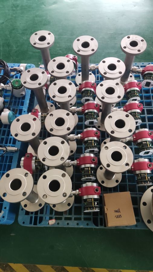
2. For online installation, first observe whether the front and back straight pipe sections meet the construction requirements. The first 10 days and the next 5 days are enough.
3. Set the installation position of the welded base perpendicular to the center of the upper pipe. Do not burn the thread of the welded base.
4. Take out the hole punch and install it. Use a drill to drill holes
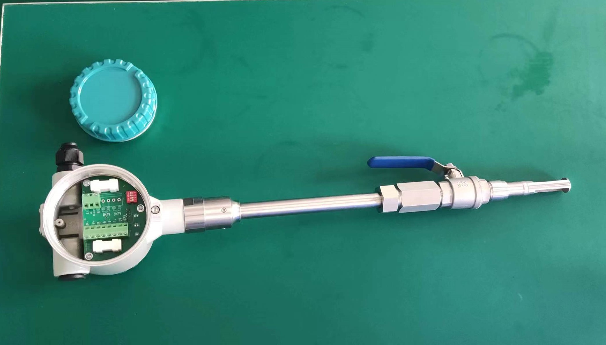
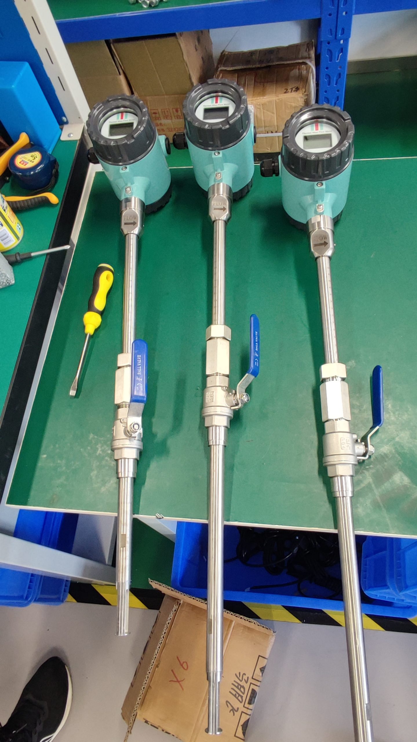
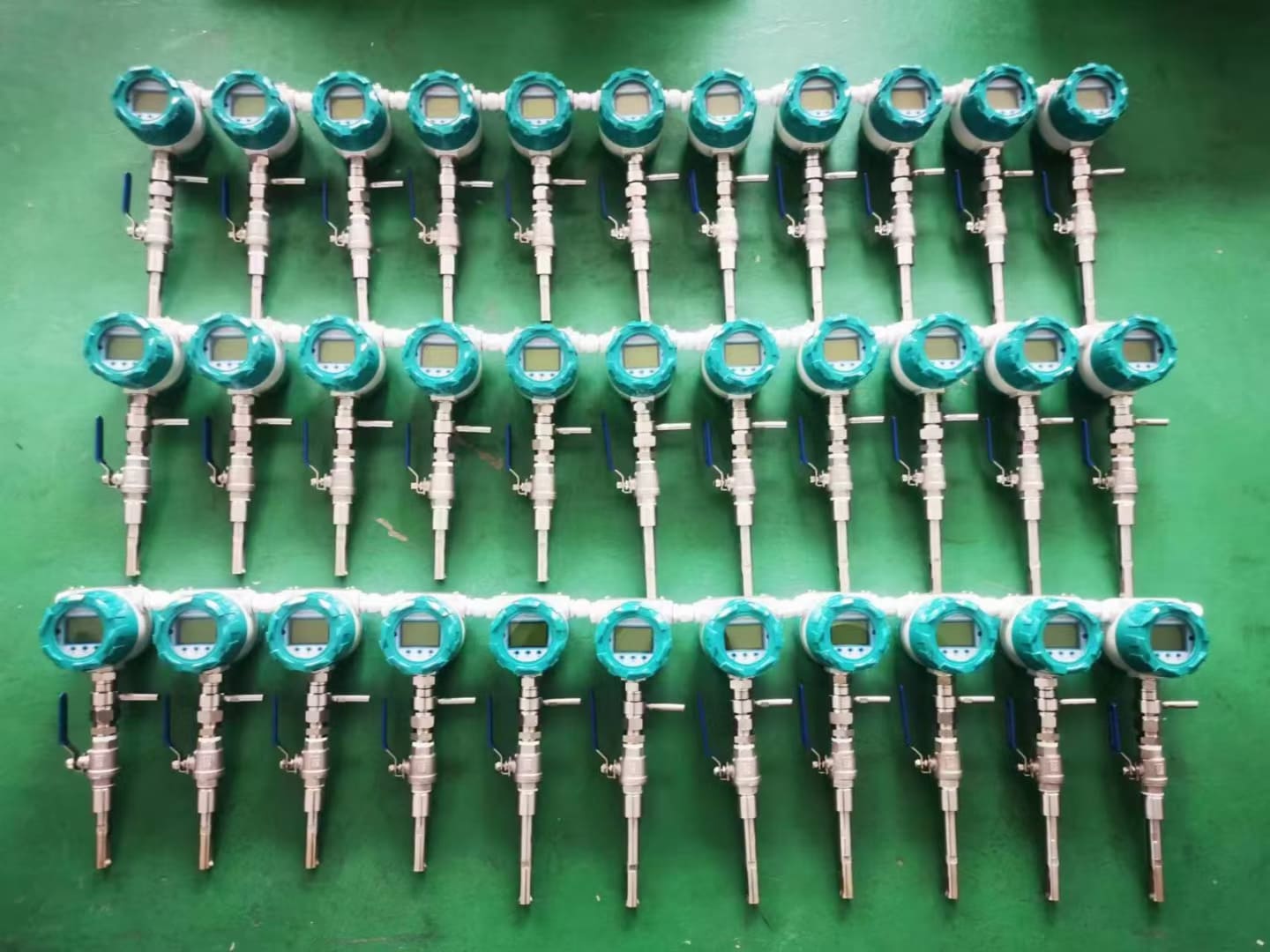
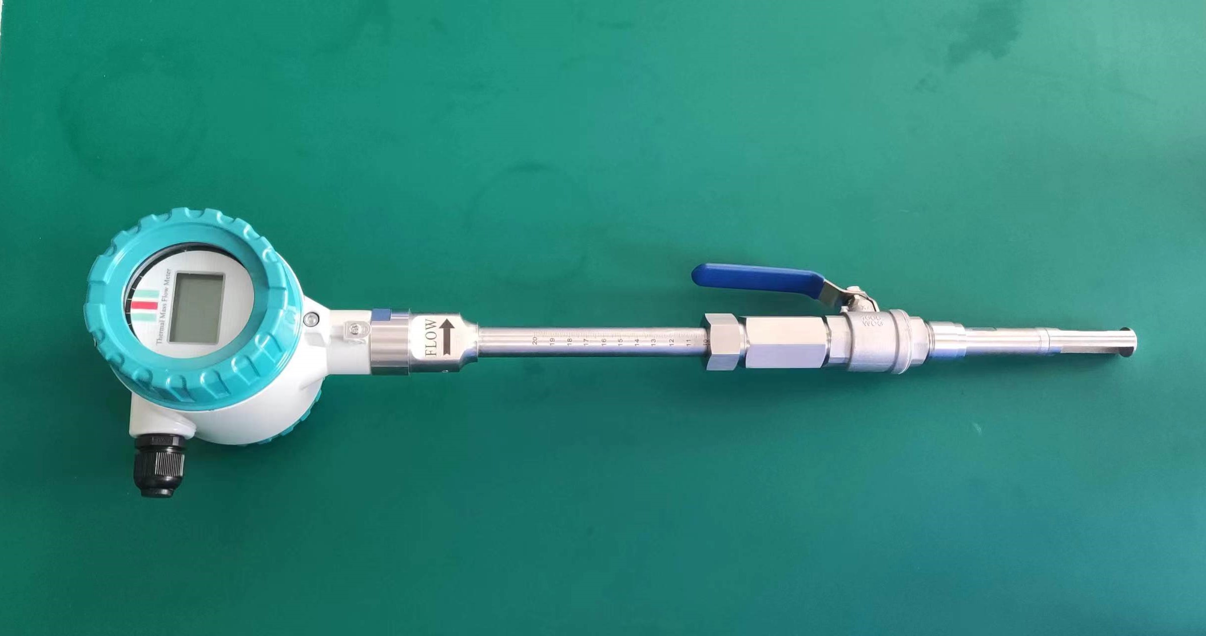
5. Take out the hole punch to close the valve, and then take out the flowmeter to insert it while slowly opening the valve, and press down with a special top pressing tool.
6. The size of the insert is generally formulated according to the parameters proposed by the customer, and the width of a thread can be left after insertion, and then the thread is tightened until there is no gas overflow.
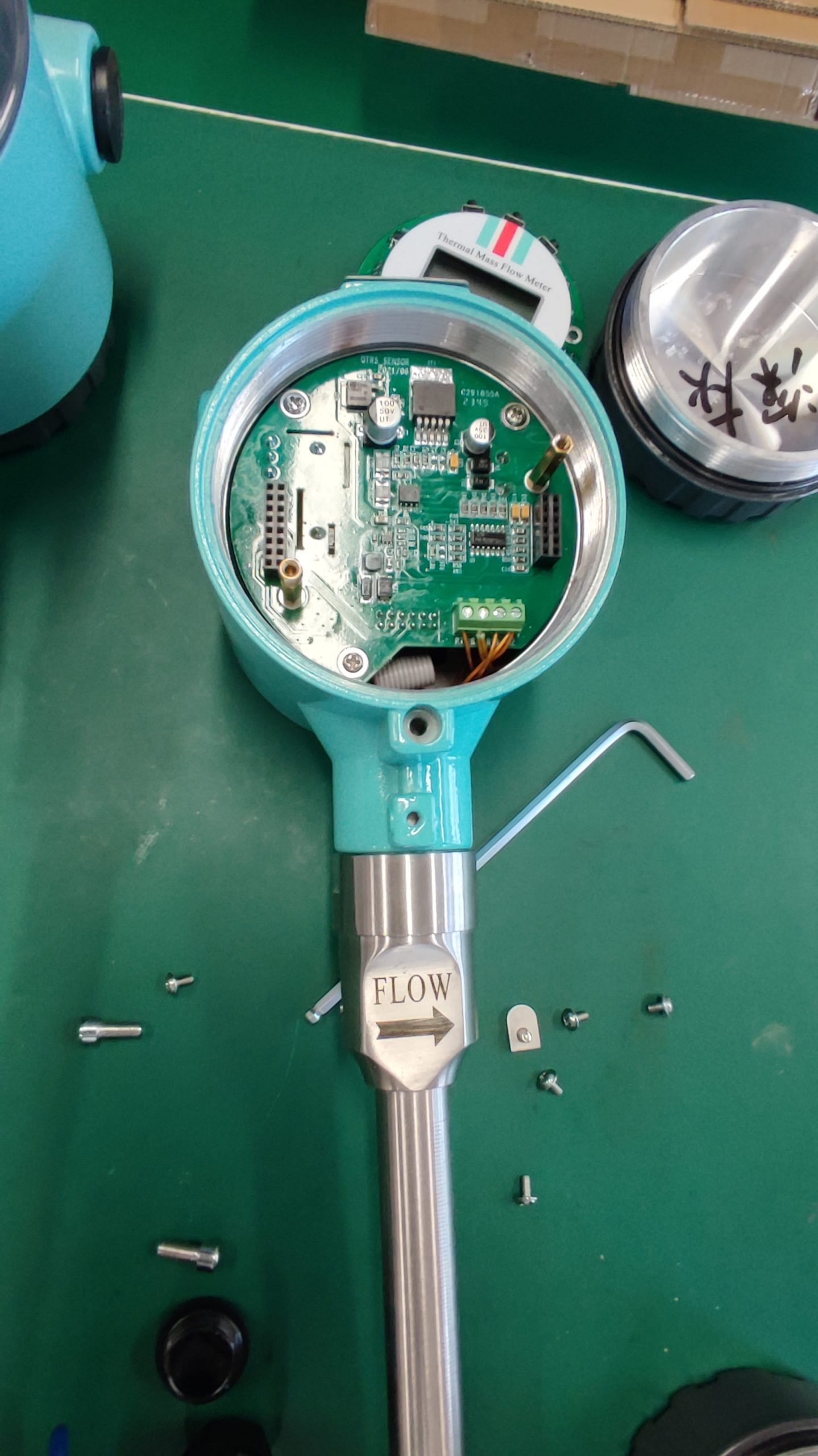
7. Then power on to see if the flow data is displayed, set the parameters of the medium, density, range, instrument coefficient and so on.
8. Connect to the 485 device and collect data successfully.
9. After testing, the debugging flowmeter is basically in line with the on-site flow data, and has reached the expected goal.


